The sequencer is an (mostly) electronic device which triggers sounds in steps in a continuously repeating sequence. The origin of such a machine is dating back several hundreds of years, since music machines were constructed. The one which resembles most to the modern computer based sequencing softwares are the barrel organs which were using long sheet of paper for programming. The actual format basically is a paper based version of what DAWs (Digital Audio Workstation) are mostly using.
This sequencer is a so called analog sequencer, because, well, because it is using analog electronic components and two ICs. This is very similar to the first electronic sequencers, except they used much more components. In this, no microcontrollers or any sort of software programming involved. It is a very simple device, but like the Atari Punk Console, it makes an excellent learning project and it can nicely control the console.
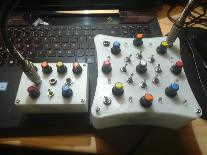
8 step sequencer with Atari Punk Console
The machine uses a CD4017 decade counter IC. It is a chip which can output 10 electronic signals on different pins, one after each other. However, we only going to use 8 steps as it is more practical musically. Many sequencers have 16 or 32 steps, it is possible to chain several CD4017 together, but I did not do that in this project. (Basically, there are much better and more sophisticated sequencer designs out there, it is more recommendable to use one of those if you are more serious).
The signals (steps) are generated by making one pin on the IC continuously high-low-high-low and so on by using a “clock” to do that for us. It can be achieved using different design clocks, but one of the simplest one is a 555 in astable mode.
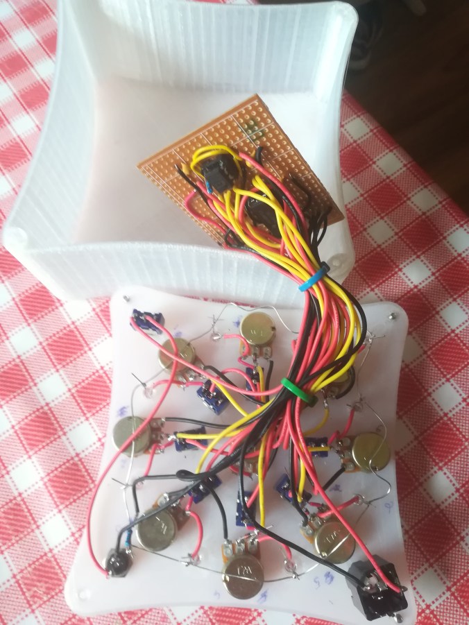
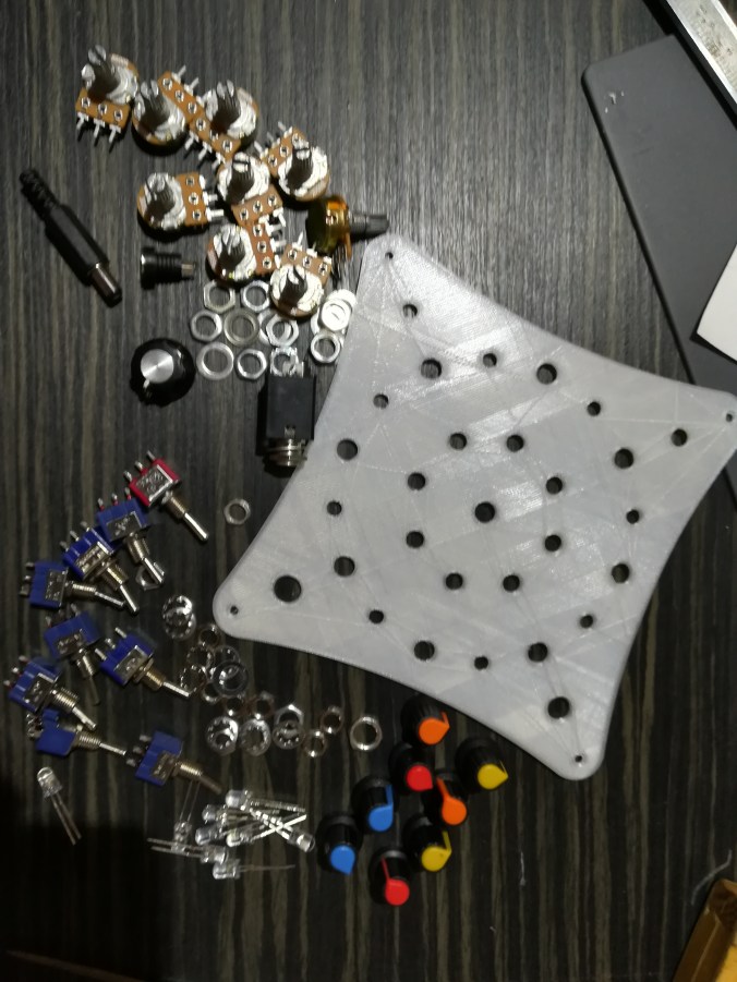
8 step sequencer components
That is the same as it was used in the console, so if you have built that, it is already familiar.
This circuit was designed by me, based on several other designs freely available on the internet.
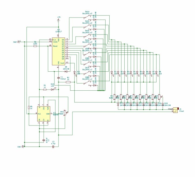
8 step sequencer schematic
Features of the sequencer:
- Variable speed control: It can control the length of each step thus the speed of the cycle
- On/Off switch for each step
- Variable voltage on each step, to control tone of steps
- CV out to connect it to the tone generator
- Standard DC power socket (9V-12V)
- LEDs for showing speed and each active step
I have designed a 3d printable box for it, which you are welcome to use.
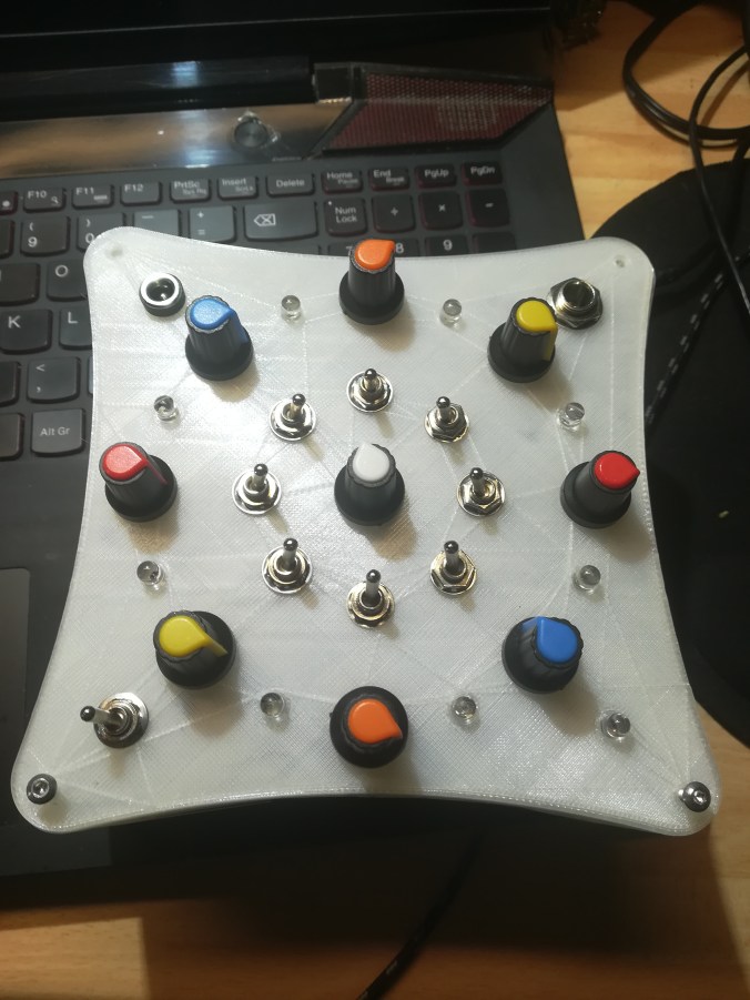
8 step sequencer 3d printed box
BOM
8 step sequencer BOM
- LEDs (any color of your choice) – 9
- 500K variable resistor (pots) – 9
- 100K resistor – 1
- 1K resistor – 3
- 1N4148 diode – 17
- SW-DPDT, on/off switch – 9
- 0.01 uf ceramic capacitor – 2
- 4,7 uf ceramic or electrolytic capacitor – 1
- CV jack of your choice, I am using 7.5mm audio jacks (same as for guitars)
- DC power outlet of your choice
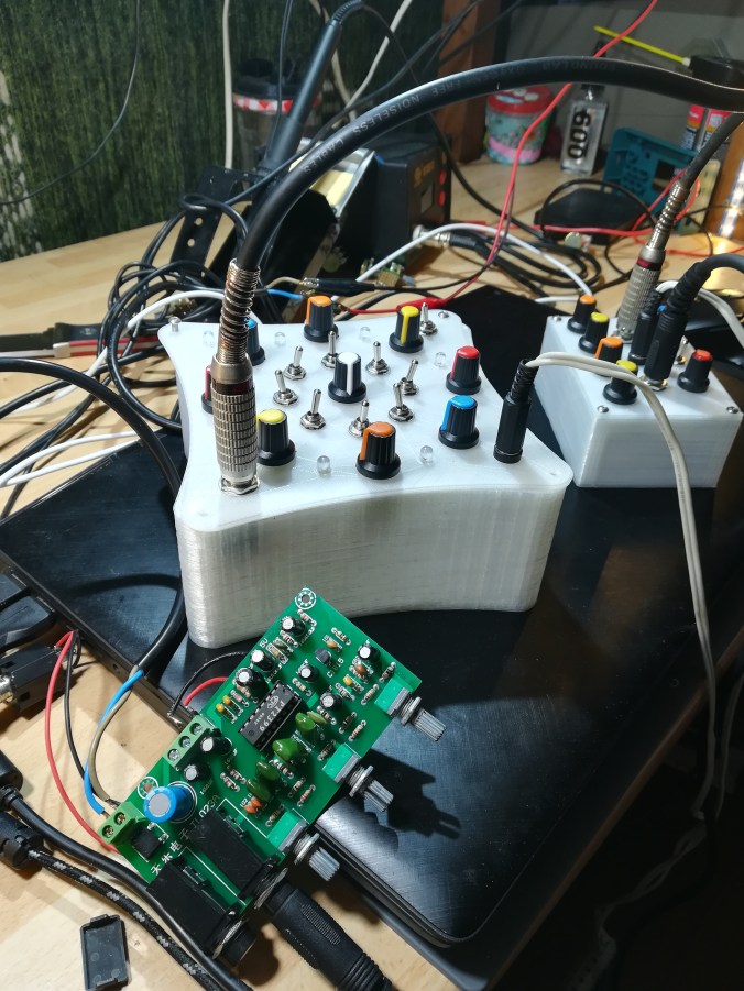
8 step sequencer + Atari Punk Console + reverb

It looks to me that the sequence is reset when any switch is off. IE: It doesn’t skip that step. Therefore the first switch is pretty much redundant. Am I right?
LikeLike
I have written a couple of lines telling why I think my drawing was right, then I had another look aaaand I am pretty sure you are right! 🙂 Off switches should go straight to ground…. I have to find my original file and correct that. The power of the internet, Thank You! I will post later on the corrected one.
LikeLike