While living in the digital age it is easy to forget about the technology which helps every day communication on our phone, tablets and PCs. Mobile phones were already almost a basic commodity and the restrictions of the virus pandemic supercharged the number of people whom are using VOIP (voice) based applications such as Zoom, Teams, etc.
In this paper, I will introduce the basic principles behind the not so new technology of transforming air pressure into binary data and back.
It is a good idea to separate the main stages of the process, in order to understand it better.
On a fundamental level, it goes like this:
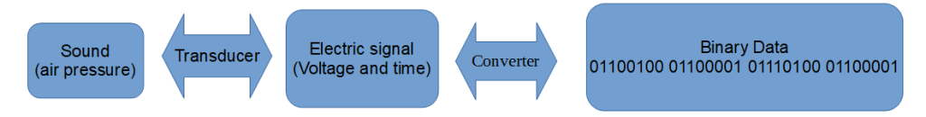
The dual directional arrows are showing that the processes of transducing and converting work both ways.
The first stage is the transformation of “sound” into “electricity” (and back). Sound is air pressure (difference) and electricity is a flow of charged electrons. Both are different form of energies. Devices called “transducers” are capable of transforming one form of energy into an other. The transducers which are being used for sound or audio recording are most commonly known as microphones.
Several solutions can be applied in microphone design, but most traditional microphones work on similar principle.
Changes in air pressure creates a physical movement of one of the microphone’s internal part and this movement using different electronic circuits creates an analogue alternating signal. The waves` energy or intensity is constantly changing with infinitely accurate values. These values correspond to the produced electrical values which than for example can be plotted on a graph or an oscilloscope against measured voltage and time.
The four most common microphone constructions;
– Carbon Microphones
based on sound pressure, loosely connected carbon (such as graphite and activated coal) pieces creates changing resistance. With DC (direct current) is power going through the connection it will became alternating because of the changing resistance
– Ribbon Microphones
A thin corrugated metal foil suspended in a magnetic field (such as between magnets) in a way that it is still movable (because of being corrugated). The current change based on the speed of motion (velocity sensitive).
– Dynamic microphones
A diaphragm attached to a moving coil suspended in the magnetic field is being used. It works on the same theory (electromagnetic induction)
– Condenser Microphones
It is based on the principals of changing capacitance. A fixed and a moveable plate electrically charged. The soundwave hits the diaphragm (the moving plate) which causes difference in distance between the plates which results in difference capacitance, according to the motion of soundwave.
– Crystal Microphones
These microphones work on piezoelectric principles. It uses a thin “sheet” of chrystal which aquire charge when compressed or twisted. It is attached to a diaphragm which follows the movement ov sound thus creates the alternating signal.
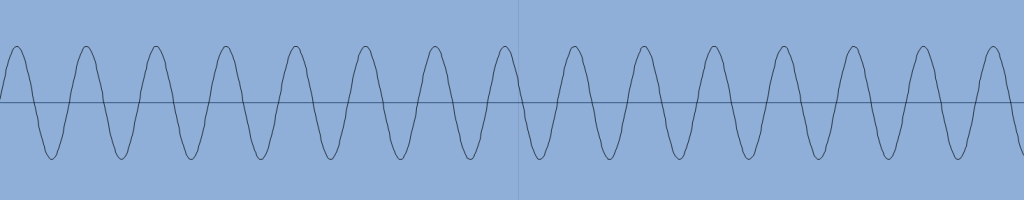
This is an example of an oscillating sine wave, that particular one is a tone of musical “A” – 440Hz; 440Hz (Hertz) is indicating the 440 “cycles” (from zero energy to 0 energy) of the soundwave in one second.
Two things achieved at the transducing step:
1. The change of air pressure (sound) is now exists in the form of alternating electrical signal which can be more easily transferred, stored and recreated.
2. Numerical values of that energy (signal) are more easily obtained by measuring voltage at given time-periods.
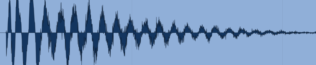
This is an example of the graphical representation of a complex soundwave (one snare drum hit). The horizontal value is time and the vertical is amplitude or intensity. As the intensity increasing and time decreasing between cycles the pitch of the sound gets higher.
In the pre-digital era, this alternating electronic signal – a representation of sound – was recorded onto different media storages like vinyl disc or magnetic tape. When we listen to these records, the signal is transformed back to kinetic energy with the use of speakers. Speakers are like reversed microphones but the speaker moves air following the electronic signal which creates the pressure difference, what we perceive as sound.
The next stage of the process of getting sound into and from our computers is to translate the decimal values (voltage and time) of our analogue sound wave into binary code, which can be processed/ stored/ etc by digital devices
Computers are using a different system for storing data or values. In the digital domain, a binary numerical system is being applied as a mathematical representation of the recorded data. A binary system is only using two kinds of numerical digit, 1 and 0. Measurements of the analogue (non digital) domain is using the decimal system (in an environment of an electrical device). The reason for that, that the circuitry inside digital devices or parts are using simple true/ false logical arguments to establish a function, which means every signal only can be either on, or off. These two states can rapidly change in equal time-periods which forms a wave. A graphical representation of such an electronic signal is a “square wave”.
This is an example of a square wave:
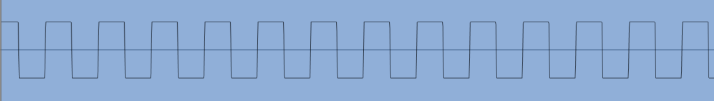
A square wave can be made audible as well, similarly to a sine wave, but with different tonal qualities. An audible (or in fact any) square wave is not entirely square in reality (a perfect square wave only exists on paper), that is because of the properties of electronic components which are generating the wave.
In terms of practical applications, we treat the square wave mathematically as it would have exact values.
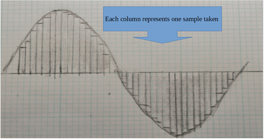
For converting an analogue soundwave`s infinitely accurate values into (near) exact binary data as close as possible, an “analogue to digital converter” (ADC) needs to be used. This is essentially an electronic circuit, which repeatedly samples and measures the voltage of an analogue signal at given equal time periods
The “frequency” is the time element of an analogue signal translating into the “sampling” or “sampling rate”. This time element of sampling indicates how often a voltage measurement of the analogue signal takes place.
The amplitude or the intensity of the analogue signal is being translated with the process of quantization. That is the process when the infinitely accurate voltage measurement is being translated into an exact (rounded up) binary code.
During the sampling process a momentary snap-shot is being taken of the continuously changing alternating signal. The sampling rate determines the number of samples taken in one second. For example, a 44.1KhZ sampling rate means that 44100 measures are being taken in one second in equal time periods (one sample in every 1/44100 second)
The Nyquist Theorem (named after Harry Nyquist, Swedes-American electronic engineer) states that for accurately represent a given sound wave in the digital realm, the number of samples taken in a second needs to be twice as high as the bandwidth of the wave (effectively the highest frequency in the wave). In practice that means that a 20kHz (which is the bandwidth of human hearing) a minimum of 40kHz sampling rate (40000 samples / second) must be used in order to get a very near accurate representation. It will produce a cross reference between two (or more) consecutive samples to determine a value.
The translation into binary; a comparator circuit is being used. This circuit compares every measurement to increasing (or decreasing during the negative cycle) reference voltage values and decides whether the particular measured value is lower (0 binary) or higher (1 binary)
The resolution or the accuracy (called the “bit depth”) of the translated binary code depends on the number of reference values used (thus the number of digits in the binary code), usually that is 8/16/24/32 bits.
The bit depth and the sample rate which ultimately will determine the quality (and accuracy) of the conversion. Higher sample rate and more bit depth resulting a better binary representation of the values of the analogue signal.
However, the recorded material size exponentially grows when we increase the quality, which less of a problem in present times than what it was10-30 years ago.
The last step missing from the entire sound – digital device – sound process is the translation from binary code back to analogue signal. For this process a DAC (Digital to Analogue Converter) converter circuit is used. This circuit, in effect is like a reversed ADC converter, which takes every digit of a binary code and runs it through of a series of voltage references (set values). Depending on the these references, the binary code operates a string of on/off switches (coupled with different resistors) which either lets the signal through or not. At the end of the circuit all the different voltages of different switches added together depending on whether it was on or off, which will give the original voltage level of the reconstructed signal.
This essay intended to tell the basics of what is happening between human – machine – human audio interaction. Although this process is known and being used since the 1970`s-1980`s, the solutions and the practical usability of digital technology was lighting fast accelerated in the last 20 years (and present) with no signs of slowing down.
References:
Books:
Huber,D.M.;Runstein, R.E. (2005) Microphone Design and Application; Digital Audio Technology in Focal Press, Modern Recording Techniques (6th Edition) pp. 115-251
Horowitz and Hill (1983) Foundations; Digital Meets Analogue in Cambridge University Press, The Art Of Electronics (3rd Reprint) Chapter 1; 9
Online articles:
Pettersen, M. (2020) `The History of Carbon Microphones and Artifacts from the Shure Archives`,
available at: https://www.shure.com/pt-BR/shows-e-producoes/louder/the-history-of-carbon-microphones-and-artifacts-from-the-shure-archives (Accessed: 20/03/21)
Cotton, J. (2007) `Ribbon Microphones On Test`, Sound on Sound, available at: https://www.soundonsound.com/reviews/ribbon-microphones-test (Accessed: 20/03/21)
Hussian Ather, S. (2020) `How Does a Digital to Analog Converter Work?`, available at: https://sciencing.com/analog-digital-converter-work-4968312.html (Accessed: 20/03/21)
Gudino, M. (2018) ` Engineering Resources: Basics of Analog-to-Digital Converters`, available at: https://www.arrow.com/en/research-and-events/articles/engineering-resource-basics-of-analog-to-digital-converters) (Accessed: 20/03/21)
